Software
Purpose and Scope
The electronic load system is a versatile testing device designed to simulate various electrical loads for power supply testing, battery characterization, and other electronic component validation. It operates in multiple modes (Constant Current, Constant Voltage, Constant Resistance, Constant Power) and provides precision control through both a local lcd interface and a remote web interface.
System Capabilities
| Feature | Description |
|---|---|
| Operating Modes | Constant Current (CC), Constant Voltage (CV), Constant Resistance (CR), Constant Power (CW) |
| User Interfaces | Local LCD interface and web-based remote interface |
| Precision Control | Digital control of load parameters with real-time feedback |
| Thermal Management | PID-controlled fan with temperature monitoring |
| Data Monitoring | Real-time voltage, current, power, resistance, and temperature measurements |
| Time Tracking | Energy consumption measurement and session uptime tracking |
High-Level System Architecture
  %%{ init: { "flowchart": { "defaultRenderer": "elk" } } }%%

  flowchart LR
  subgraph subGraph0["User Interface"]
      direction TB
          C1["Encoder Reading"]
          C["User Interface"]
          C2["LCD Display Update"]
          C3["WebServer Communication"]
    end
  subgraph subGraph1["Power Control"]
      direction TB
          D1["ADC Reading"]
          D["Power Control"]
          D2["Parameter Calculation"]
          D3["DAC Configuration"]
    end
  subgraph subGraph2["Monitoring and Protection"]
      direction TB
          E1["Temperature ADC Reading"]
          E["Monitoring and Protection"]
          E2["Fan Control"]
          E3["Overload Protection"]
    end
      A["Start"] --> B["System Initialization"]
      B --> C & D & E
      C --> C1 & C2 & C3
      D --> D1 & D2 & D3
      E --> E1 & E2 & E3
- ADC: Measures voltage, current, and temperature
- DAC: Controls the load level
- Analog Switches: Configures operating mode and relays
- Fan & PID Controller: Manages cooling based on temperature feedback
- RTC: Tracks time for energy and uptime measurements
Key Components & Data Flow
  %%{ init: { "flowchart": { "defaultRenderer": "elk" } } }%%

  flowchart TD
  subgraph s1["Acquisition"]
          ADC["ADC: Voltage, Current, Temp"]
          RTC["RTC: Timestamp"]
          Enc["Encoder + Button"]
    end
  subgraph Control["Control"]
          MCU["ESP32"]
          FSM["FSM"]
          PID["PID Control (Fan)"]
    end
  subgraph s2["Generation"]
          DAC["DAC"]
          SW["Analog Switches"]
    end
  subgraph s3["Visualization"]
          LCD["LCD"]
          WS["WebSocket"]
          LED["Integrated LED"]
    end
      ADC --> MCU
      RTC --> MCU
      Enc --> MCU
      MCU --> FSM & PID & LCD & WS & LED
      FSM --> DAC & SW
      PID --> FAN["Fan"]
Main Loop Operations
The main control loop performs several critical operations during each iteration:
  sequenceDiagram
      participant Main as "Main Loop"
      participant Meas as "Measurements"
      participant FSM as "FSM"
      participant Fan as "Fan Control"
      participant UI as "UI Updates"
      participant WS as "WebSocket"
      loop Each loop iteration
          Main->>Meas: Read voltage, current, and temperature
          Note right of Meas: Calculate power, resistance
          Main->>FSM: Run FSM with updated measurements
          Note right of FSM: Execute mode-specific operations
          FSM-->>Main: Update outputs (DAC, relays)
          Main->>Fan: Update PID controller
          Note right of Fan: Adjust fan speed based on temperature
          Main->>UI: Update LCD screen
          Main->>WS: Send status updates
      end
Operating Modes
- Constant Current (CC): Maintains a user-defined current
- Constant Voltage (CV): Maintains a user-defined voltage
- Constant Resistance (CR): Simulates a fixed resistance
- Constant Power (CW): Maintains constant power dissipation
Each mode uses specific DAC settings and switch configurations, managed by the FSM.
User Interfaces
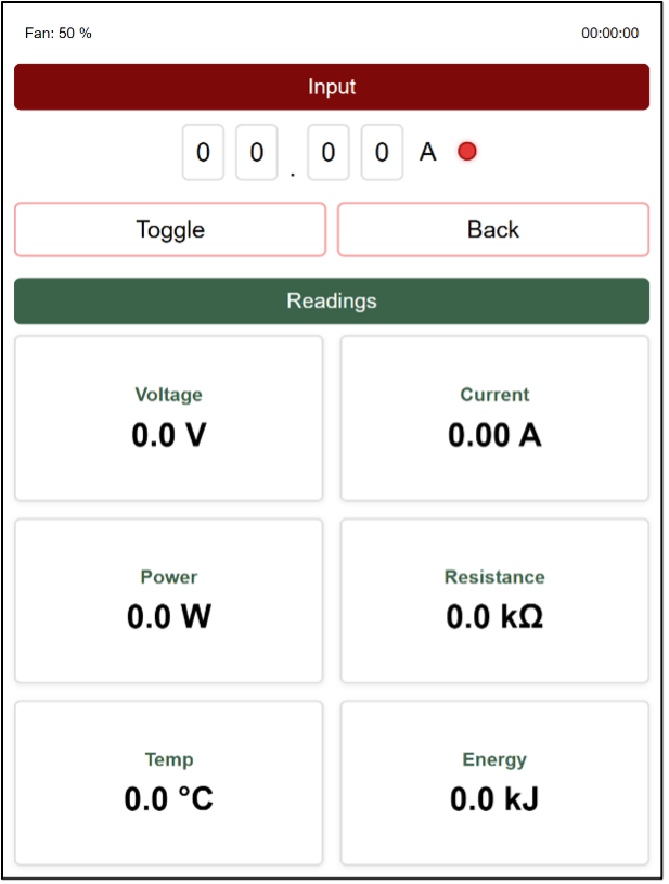
LCD Interface
- Built with LVGL
- Main menu for mode selection
- Mode-specific screens for parameter adjustment
- Real-time measurements & status indicators
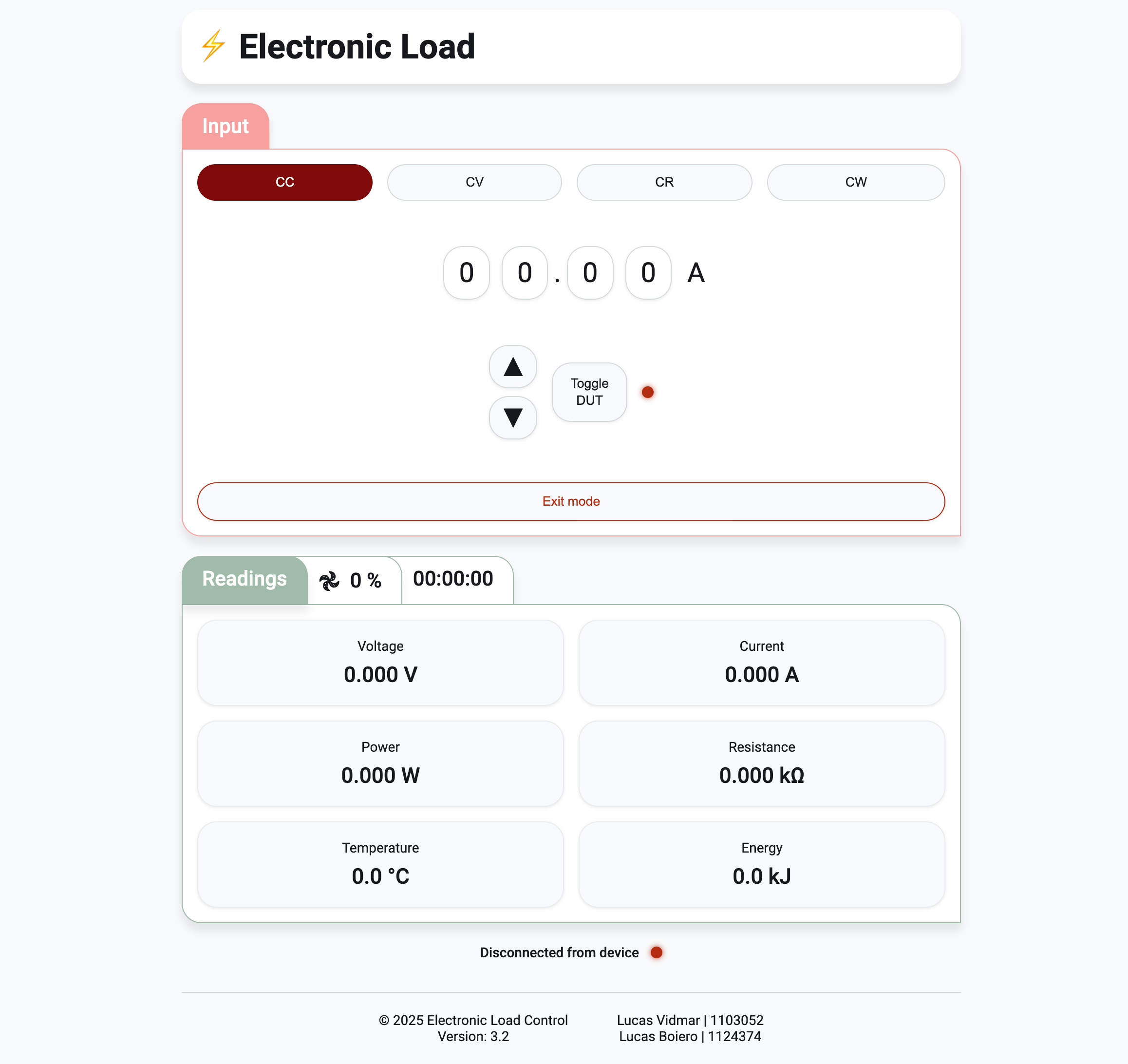
Web Interface
- ESP32-hosted web server
- WebSocket for real-time updates & JSON commands
- Full remote control of modes & settings
 |
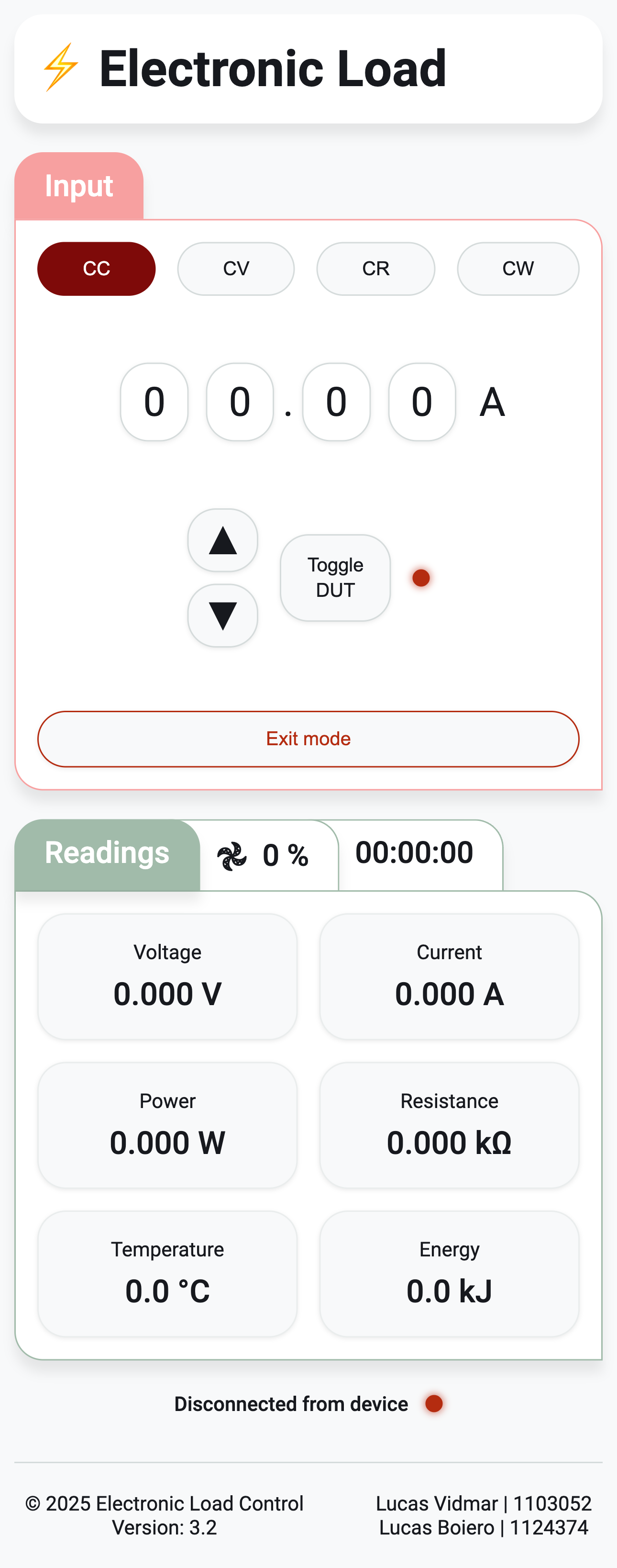 |
| Desktop | Mobile |
Control & State Management
- FSM States:
MAIN_MENU,CC,CV,CR,CW,SETTINGS - Transitions: Encoder/button or WebSocket commands
- Actions: Configure hardware and update UI based on state
Hardware Components
| Component | Class | Purpose |
|---|---|---|
| Digital-to-Analog Converter | DAC |
Controls load level via gate voltage |
| Analog-to-Digital Converter | ADC |
Measures voltage, current, temperature |
| Analog Switches | AnalogSws |
Configures mode-select relays |
| Cooling Fan | Fan & PIDFanController |
Maintains safe temperature |
| Real-Time Clock | RTC |
Tracks time for energy & uptime |
| LCD Display | LVGL_LCD |
UI |
| Rotary Encoder | Encoder |
User input for parameter selection |
Development Environment
- PlatformIO (ESP32 target)
-
Libraries:
- LVGL & TFT_eSPI for LCD
- AsyncTCP & ESPAsyncWebServer for web interface
- ArduinoJson for JSON handling
- Version Control: Git (src/main.cpp, etc.)
Conclusion
The electronic load system offers a modular and extensible platform for testing power supplies, batteries, and electronic components. With four operating modes, dual user interfaces, real-time feedback, and robust thermal management, it serves both educational and professional applications as a versatile test instrument.